Categories
Tech

York Compressor on a ’73 FJ40

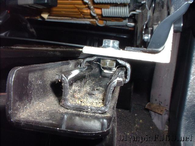
I recently installed a snow plow on the front of my ’73 FJ40. It is a nice lite weight plow made by Moose Industries in Alaska. They are no longer in business but the owner, relocated to the Portland, Oregon area, had his last stock of them for sale on Ebay last winter after we had our big snow. The plow uses a pneumatic cylinder to lift the plow and gravity to drop it and has most of the features of the larger hydraulic plows commercially available.

I was going to use a small compressor and a tank, but was worried about having enough volume for short runs and constant lifting of the plow. Next I looked at the ViAir 450 series compressor with 3 gallon tank. This would have been the easiest approach and is a very nice constant duty system, but I didn’t want spend the money. I took a quick trip to the wrecking yard and found a used compressor from a 1982 Volvo sedan. This compressor also had the P/S pump and brackets. The ’82 Volvo used a Saginaw P/S pump but has a metric fitting on the back and a wide pulley. This is the pump I used in my P/S pump conversion on a ’84 FJ60. The York compressor is also used on many American made cars and trucks, including many of the full size Jeep’s and Ford trucks.

DSCN4141

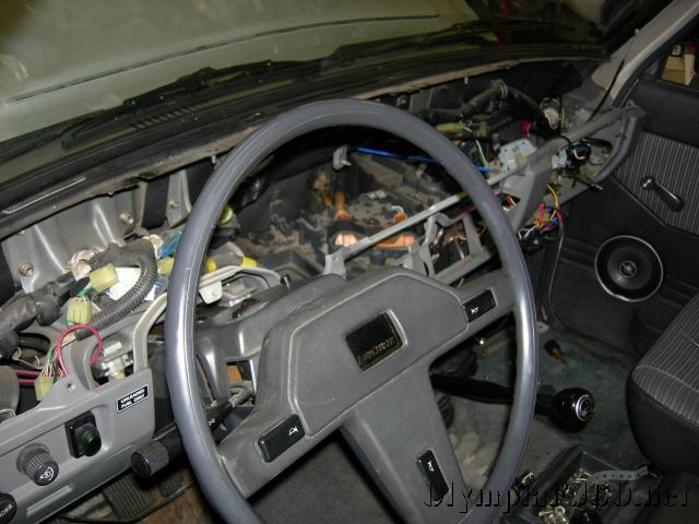
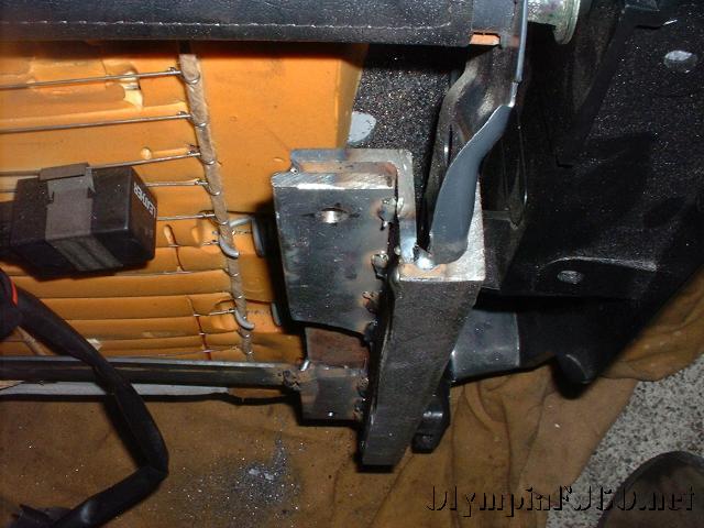
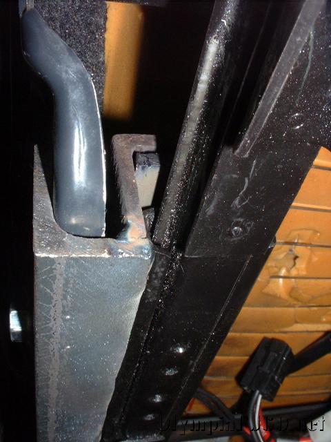
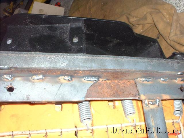
I decided to mount the compressor on the passenger side of the engine, in place of the AIR pump. on reason I chose this side is because I didn’t want to loose the stock air cleaner housing. I also designed the bracket to fit on the 2F engine that I plan on putting in the FJ40 in the future. I used the AIR pump clean air port on the housing as my clean air pickup for the compressor.

DSCN4178

It’s important to keep the Volvo bracket if you can get it. It will save a bit of cutting and drilling. I cut the top P/S mount off of the bracket and flipped it over. For the cylinder head plate, I made a paper pattern to clear the #1 spark plug wire and traced it to a piece of 3/8″ plate I had. I then measured the offset for the compressor bracket and matched the two together. With the stock battery tray in place I had about 2″ between the york compressor and the cylinder head, just enough room to fit the bolts. Two bolts mount directly through the cylinder head plate, the third hole is through the compressor plate, a 1 1/4″ spacer and the cylinder head plate. The two plates are connected in three other spots with gussets and braces. I also used the belt tensioner from a 3FE A/C belt.

DSCN4192

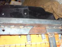
For the air tank I found a used Semi Truck air reservoir at Northwest Truck parts. It’s about 3 gallons and has a larger diameter than I wanted but the price was right.  It is mounted under the rear of the truck just behind the frame cross-member.

For the manifold, I used brass fittings from the hardware store. For the air lines I just used 1/4″ copper tube and 3/8″ flare fittings.

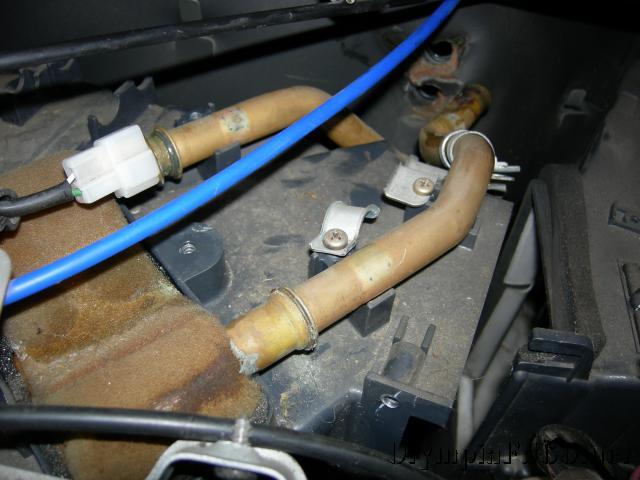
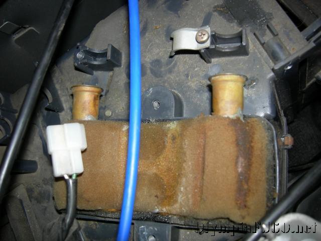
The compressor is controlled through a Viair pressure switch and relay.  There is also a coalescing filter and pressure relief check valve.  The coalescing filter removes any excess oil from the lines.  There will be a return plumbed in to put the filtered compressor oil back into the compressor.  The relieve check valve allows the compressor to start without any head pressure.

Categories
Outdoors Tech Vehicles

Camp Bug I gets a few new accessories

Getting ready for a few camping trips I decided to update a several items on the trailer.

The first was to install a door for a little more storage space and so I can check on the batter charge condition without having to open the top and remove the inside shelf.  I was able to find the correct size hatch on Ebay for a reasonable price.

trailer updates 1
trailer updates 2

I also installed an outdoor shower box for rinsing off and the occasional shower. I also have a shower enclosure and use the solar shower bag. I like using the bag because it prevents any one from over using the water. The shower will be plumbed into the lines going to the sink in the rear.

trailer updates 4
trailer updates 5

I also wanted to add propane bottle bracket. I kept looking (as others have) for the correct solution for my trailer. I was going to use the XL Quick Fists as they have and extremely high rating, but I decided I wanted the primary tank on the tongue rather than against the box. I ended up bending some 2″x 3/16″ strap on my harbor freight bender. Making 90* bends is about all I use it for and it does the job well. I made a 1/4 cage crossed with a full cage that is hinged on the top and uses a heavy locking clasp. It is bolted to the tongue.

trailer updates 6
trailer updates 3

For the spare tank I used the XL quick fist straps. They are just big enough for the smaller tanks and hold it quite well.

Photo_080409_sm_003

The last thing I did before the trip is the installation of the under body water tank and gray water tank. This opened up considerable storage space and lower the COG even more, as well as move the water weight centered over the axle.

The water tank is just a basic unbaffled 20 gallon tank. All fittings are customizable. I just put a vent, drain and fill fitting.

water tanks 03.

The tank was fitted up for marking holes then temporarily strapped up with plastic plumbers tape.

water tanks 05
water tanks 06

For the waste tank I decided to use a standard RV drain valve. Time will tell if this was a good idea. It sits pretty tight up to the frame behind the spring shackle. This tank came pre-molded with a 3″ drain and is tapered at the back, just enough to tuck up to the rear frame member. I had a 1 1/4″ fill and 3/4 vent fitting added. I got a 3″-1 1/2″ adapter and the valve at the local RV repair store and the ABS fittings at the hardware store.

water tanks 02
water tanks 08
water tanks 09

For the tank straps I used some 1/8 x 1.5 bar, added some bends for soft corners and bolted it up to the frame using the same Rivnuts I used in the decking. This is how my Land cruiser gas tank is mount so I think it will be adequate for the trailer.

There is just about the same amount of room between the bump stops and the springs as there is between the axle tube and the tank. I may add a little aluminum skid shield to protect the hoses and fittings. This would be attached to the tank straps.

Here are a few pictures of  the tank straps. Turned out pretty well. No sign of failure yet but the center of the water tank may need a little more support.

Photo_080409_sm_007
Photo_080409_sm_006

I was able to gain a lot of space in the trailer by moving the water tank underneath. I rearranged the batteries to help maximize this space.

Photo_080409_sm_001
Photo_080409_sm_002
Photo_080409_sm_004

Here are a few of the trailer in action on a recent camping trip to the Naches Ranger district.

Naches 2009 sm 04
Naches 2009 sm 03
Naches 2009 sm 06
Categories
Outdoors Overland travel Tech

Off-road Tent Trailer Build, Part3

The trailer tent has arrived. I set it up quickly or some pictures and get a first impression. Of course it was raining so I had to set it up in the shop. I was not able to open the annex and install the walls but the main tent fit (just barely) and I like what I see so far. Well made with heavy sippers and double seams. I have some questions on the travel cover but everything else looks pretty good. Now I just have to figure out how I’m going to mount it to the trailer. I think a bit of extra bracketry is required and will have to pack the tent back up and flip it over to get a better idea.  I will get more pictures one I get it permanently mounted and can set it up outside.

trailer_tent_02
trailer_tent_01
trailer_tent_03
trailer_tent_04
trailer_tent_05
trailer_tent_06
trailer_tent_07
trailer_tent_08
trailer_tent_09
trailer_tent_10
trailer_tent_11
trailer_tent_12
trailer_tent_13

My minimum order is 10, so I think 5 people and I will have to nearly full price. If I can get 8 or more, I will be able to give about 20% discount I think.  If you are interested in being part of the initial order please let me know by using the contact form.

Still waiting on ocean shipping rates. Also looking into the need for fire retardant fabric before I announce a price.

The size of the tent closed is 90″ (~7.5′) long, 66″ (5.5′) wide and between 6″-12″ tall. The width was selected because that is the width of my trailer outside fender to outside fender. I believe the M416 is roughly the same. The base is designed to sit 54″ off the ground. Open, the tent is 17′ wide and 15′ long (7.5′ each for main room and awning). The peak is 8′. The tent fabric is 10oz rip stop poly cotton canvas and the floor is 13oz PVC. Polls and ladder are steel. The base is 3/4″ marine grade plywood with a metal frame under for added support. There are two hatch doors in the base for easy access to trailer storage once setup. There is a 3″ foam mattress. The entire tent weighs roughly 350 lbs.

I am still working on the mounting. I am thinking of offering a mounting frame at additional expense or having the customer provide their own mounting method. The frame would fit customers trailer and have hinges, latches and struts.

Categories
Tech

FJ60 Heater Core Replacement.

camera-038

Having to install a heater core in the FJ60 Land Cruiser can be one of the worse jobs we have to do. It doesn’t sound bad, but as you start looking into all the steps it becomes apparent this isn’t just a simple operation, or is it. The FSM calls for the dash to be removed, then to remove the A/C evaporator module (if equipped) then the heater core module.

camera-036

The heater core is held in its case by a bracket across the top and little clamps over the tubes. The tubes are held in the heater core with little clips. With the tubes attached there will not be enough clearance to remove the heater core with the case in the vehicle.

camera-037

While you will still need to remove the entire dash and heater ducts. If you remove the tubes first, pull the cases away from the firewall you will be able to remove the heater core without disconnection the A/C. I used a pair of screw drivers to pry the somewhat stuck heater core out of the case. Once out I made sure to clean out any old coolant that was sitting in the bottom of the case. The new heater core did not come with any of the foam that is used to seal the core in the case. All that my local parts store had was camper tape and appears to work just fine. The new core also didn’t come with new o-rings. Having an assortment on hand is always handy and I was able to find two of the proper size.

With the new heater core installed and tubes mounted in place the dash was reassembled, hoses connected at the fire wall and the coolant refilled. It may be advisable to attach the hoses and refill the cooling system before finishing the dash work to spot any leaks.

Categories
Tech

Toyota FJ60 Land Cruiser Seat Upgrade

I have been less impressed with the seats in my ’87 FJ60 since I bought it. They are thinly padded with a weak frame (for someone of my size). I installed seats from a Volvo 240 wagon a few years ago and this was a huge improvement. Better padding, solid frame, just not that adjustable. I regularly pursue the local wrecking yards in search of a better seat that will fit. I have looked at other Toyota seats, BMW, mini-van and others as well. I have never found seats that I thought would both fit, and meet my needs. During a visit to my neighbor hood wrecking yard last summer I came across a Mercedes M350 that had been badly wrecked. They looked like they would fit and both the drivers seat and the passenger had 8 way adjustable power as well as seat heaters.

I never did a write up of the Volvo seats but I will include a few pictures before continuing onto the Mercedes seats.

custom-volvo-seats-004

The factory slider was removed and a bracket was made to fit the Toyota slider to the seats.

custom-volvo-seats-001
custom-volvo-seats-003
custom-volvo-seats-005
custom-volvo-seats-006
custom-volvo-seats-009

I am 6’6″ and the first bracket made the seat sit too high. This left my head in the headliner with the seat back at a comfortable position. I figured I could lower the seat another 1.5″ and modified the drivers bracket to fit this.

custom-volvo-seats-013
custom-volvo-seats-014

custom-volvo-seats-017

This bracket was pretty tight to the slide and it was difficult to adjust when slid all the way back.

Now for the Mercedes seats. This was a much easier bracket to make. Instead of welding angle, all I had to do was bend up some 2″x.25″ bar stock purchased from Lowe’s. To bend the bar I used a little bender from Harbor Freight. This was the max size the bender could handle but it was adequate.

I drew up a sketch in Google Sketchup with measurements from the truck floor. Now, the floor pan on the ’86 and ’87 trucks is different than the earlier trucks. The earlier trucks have a higher raised spot that the sliders attach to. This may be enough that these seats would not fit for tall people.

Once I had my brackets I drill the floor mounting holes and loosely bolted them to the floor. I then set the drivers seat in the truck to get an idea of location. Once selected, I marked the brackets for drilling the seat mounting holes. Brackets bolted to the seats it was time for test fit. I got lucky on this one and the seats fit. They still sit a little high in the back and I have to have the rear adjusted all the way down with the front all the way up. I have room to lower the back of the bracket about 2″. I will add photos to this article once I have reworked the brackets.

Now for the wiring. There are two types of seats in the ML350, power with memory and just power. I ended up with the power with memory. The power only may have been a little easier to wire but this is what I had. On the power with memory seats, each seat has a power seat module (PSM). This is a little relay/computer box that is attached to the bottom of the seats. All of the motors and motor sensor connect to this box as well as input from the vehicles extended activity module (EAM). My seats came with the PSMs (be sure to get the harness from the car to the PSM). The EAM performers many functions in the car none of which are needed here except power to the PSM.

It was a little confusing at first but I figured out the wiring. There is two power inputs to the PSM, 12v+ 30amp to the seat functions and 12v+ 20amp for the seat heaters. There is also a ground wire, and two wires to the heated seat switch. There are two positions for the seat heaters, regular and rapid heat (hi). This again had me confused for a while as I kept trying to apply 12V+ to the wires with no action from the relays. After looking at the wiring for a 4th or 5th time, going to the computer to do some additional research, it dawned on me that the heater relays may be controlled with 12v-. After a few tests I had completely functioning power heated seats.

Is it worth it? I think both the Volvo seats and the Mercedes seats are a great improvement. Not only do they look good (leather), but the are more comfortable and have a much more rigid frame. I think with the ease that the Mercedes brackets were made and how nicely they fit in the 60, the would be my preference every time. They may be much harder to find though.